
Do you know about the datalink layer of OSI Reference Model, know about the functions of data link layer. If you don’t know then you will get complete information in this article. We will learn about the importance of the data link layer in computer networks. Please read this article completely.
What is Datalink Layer?
The data link layer is the 2nd layer in the OSI model from the bottom or you can say that it is the layer between the network and the physical layer. This layer helps in sending data from one node to another.
The internet is a combination of networks glued together by connecting devices. If a packet is to travel from one node to another node, it needs to pass through these networks. Communication at the data link layer is made up of five separate logical connections between the data link layer in the path.
The important thing in this is what is the responsiveness of the data link layer. All 7 layers of OSI reference model network are working well, so how does the data link layer help in moving the data from one place to another? This will be known today in this article.
Functions of Data Link Layer in OSI model
The main functions of data link layer in OSI model is to help to transfer data from host to host or node to node. A network connects to another network through some networking devices, like the router. A network is made up of different types of topologies.
Every topology has different nodes connected. When sending data from a node of one network to a node in another network, the data link layer first sends data from the sending node to the router. The router then sends the data to its next node or router which is connected to the receiver network. The router that receives the data finally sends that data to the receiver node.
With the help of the data link layer, all the nodes in a network can interchange data with each other. In this, only the physical address or MAC address of that node is needed.
There are many responsibilities or functions in the data link layer. Some important functions are mentioned below.
Framing in Data Link Layer
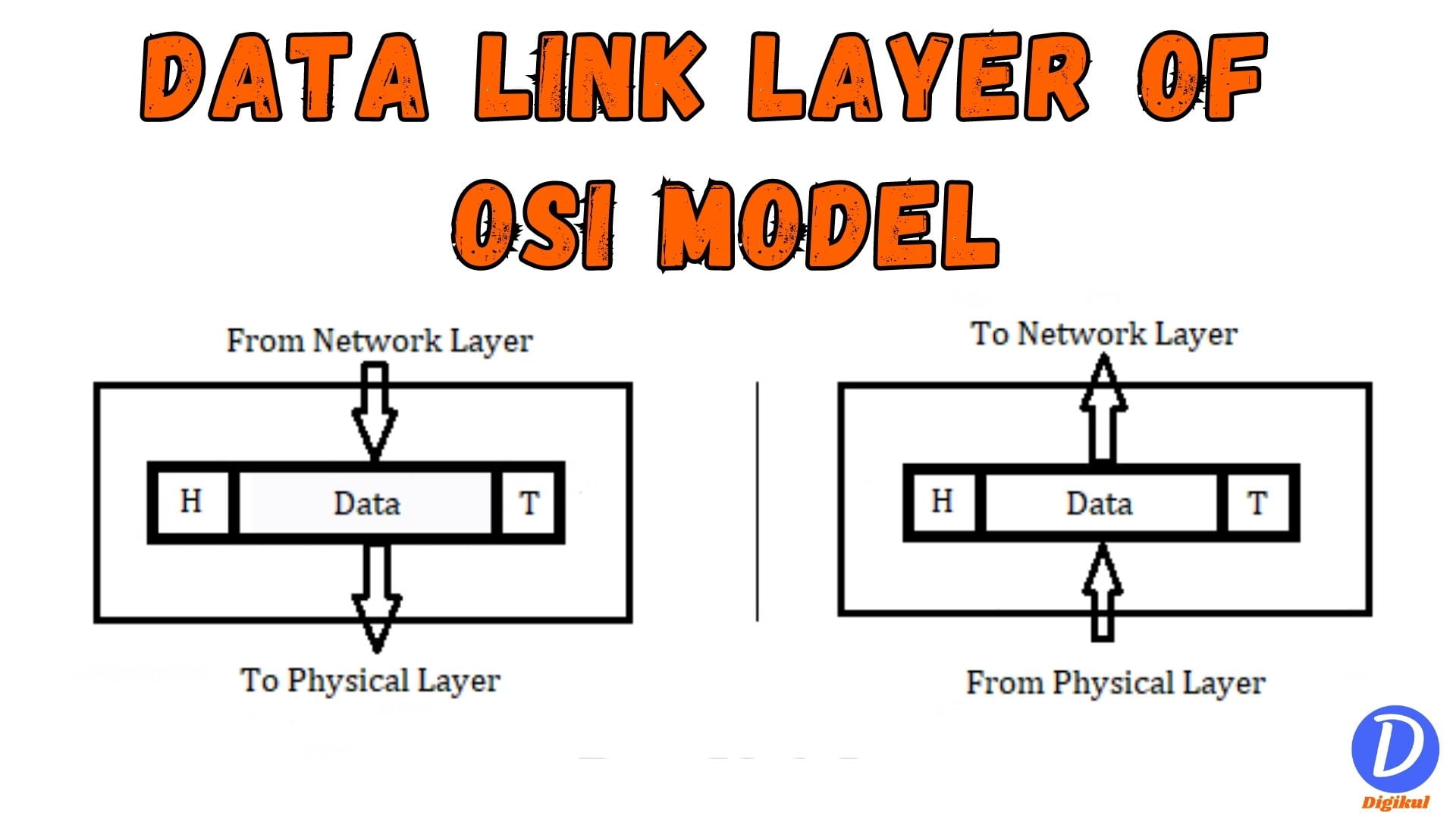
All of you will know that data or information is sent from the network layer to the data link layer. After that, the data link layer sends it to the physical layer and in the same way that data reaches the destination network.
When data packets arrive at the data link layer from the network layer, that packet is divided into a fixed size. After that, the data is pulsed inside a special frame. So that the data can reach the destination safely.

Framing in Data link Layer, the header is installed at the front, and the taller is installed at the end of the frame. This allows the frame to identify itself, in which the receiver can easily locate its data frame.
For example, when a child is born, it is given a name by its parents. So that the child can be identified. That name has a first name and the last name. Similarly, in a frame, there is a header in the first and there is a taller at the end.
Flow Control in Data Link Layer
Flow control in data link layer is another important function. With this, the data frame going from one host to another is controlled.
This flow control technique is used to control when data flows from one source host to another. If there was no flow control, the flow of data from node to node would be much faster. Due to this, the receiving node cannot control that data frame. Then the packets will be automatically lost.
For example, if the call continues on your mobile, then the old call record which is recorded gets deleted automatically.
To overcome this problem, flow control is used in the data link layer. There are 3 types of protocols used in the flow control function to control the data.
- Stop and Wait ARQ Protocol
- Go Back N ARQ Protocol
- Selective Repeat ARQ Protocol
Stop and Wait Protocol
In this stop and wait protocol, the sender can only send one data frame to the receiver at a time. After that, the sender waits until the receiver sends an acknowledgement of receiving the data.
In this, the sender has to wait until the receiver gives the acknowledgement. Therefore, this protocol has to wait for a long time. So, its bandwidth or efficiency is very low. In this protocol, only one data frame is sent to the receiver at a time and only one acknowledgement is received from the receiver.
The sender sends the data frame to the receiver but unfortunately, that data frame got corrupted in between. Then the receiver is unable to receive the frame and does not send an acknowledgement. From this point, the sender waits for some time and retransmits that data again.
Go Back N ARQ Protocol
In this Go Back N protocol, multiple frames can be sent simultaneously to the receiver end. The sender can send (2n– 1) frames simultaneously according to his calculations. n means the number of bits to represent window size.
But the receiver can only send 1 acknowledgement at a time. When the sender simultaneously sends many data frames sequentially to the receiver. The receiver after receiving all those frames gives feedback to the sender to send the next frame. This feedback acknowledgement is called a cumulative acknowledgement frame.
The data frame which is sent by the sender is passed to the receiver in a sequential manner. If the sender sends 1, 2, 3, 4, or 5, data frames to the receiver, but due to some problem, the number 1 data frame does not reach the receiver, and all the rest reach.
The receiver receives the data in sequence mode. But due to the lack of a 1 number data frame in all these data frames, the receiver rejects all the others. Because of this, the sender will re-transmit as many frames as it was sent earlier.
Selective Repeat ARQ Protocol
In the selective repeat protocol, multiple frames can be sent to a receiver at a time. This protocol is a combination of the Stop and Wait protocol and GO back N protocol. In this, as many frames can be sent by the sender, that’s many frames can be sent from the receiver.
The window size of the sender and receiver is (2n-1 ). Where n is no of bits represents the window size.
In this protocol, when the sender sends the data frame to the receiver. If some of this data packet is lost in the middle and all other packets reach the receiver, then the receiver accepts it. After that, the receiver sends the acknowledgment to the sender to resend the lost data frame.
It accepts out-of-order frames. Because of this, the retransmission is negligible or is 1. Its design is complex as compared to other protocols.
A data frame is sent to the receiver. But due to the noise in the path, an error occurs in that data frame. When the receiver checks this data frame, then he will come to know that there is an error in the data packet. Therefore, the receiver sends a negative acknowledgement to the sender. It is well known that the sender does not have to wait much time.
Error Control in Data Link Layer
In this data link layer, when data travels from sender to receiver, at some point in time there is an error in the data due to some noise in that path. To fix or catch that error the error control method is used. Here the method is more commonly used in local area networks and wide area networks.
Data is transmitted from node to node in the data link layer. Therefore, it uses the Cyclic Redundancy Check (CRC) method. It is helpful in this that the error can be detected as soon as possible. If data is passing from one hop to another and in the second hop it is detected that there is an error in the data, then it does not take much time to correct this error by cyclic redundancy check.
Access Control
In the data link layer, all nodes living in a network can transmit data between themselves, without using the network layer. In this data link layer in OSI model, all the nodes are connected by a single cable.
If there are 5 nodes in a network and all are connected to the same thick wire. If the number 2 node is transmitting data. At the same time, no 3 node also transmits the data. Then both the data contain the collision and all the data is lost.
The access control method is used to solve this problem. CSMA/CD, CSMA/CA, ALOHA, Token, etc. are used in the access control method. Therefore, when a node is transmitting data, the same node accesses the entire channel/path. That’s why all other nodes are not able to transmit data, only receive the transmitted data.
Physical Address
The physical address is also called the MAC address. This address is of 48 bits. MAC address is different in all the nodes and the address of that node is fixed. This means that, if all nodes in a network want to transmit data to each other then data can reach the correct receiver.
This method only works within the same network. If transmits data to another network, the MAC address cannot be used in it, logical address is used in that cash.
Also Read:
- 7 layers of OSI Reference Model
- Importance of Physical Layer
- Data link layer in OSI model
- Important Functions of Network Layer
- Major functions of Transport layer in Network
- Session layer in OSI Model
- Presentation layer in OSI model
- Application Layer in OSI Model
Conclusion
The data link layer in OSI model is located in between the network layer and the physical layer. In today’s article, we have given you complete information about the functions of Data Link layer in OSI model. In this article, all the data link layer functions asked in the exam are given in detail.
Hope all of you have got the right knowledge about functions of Data Link layer in OSI model from this article. If you do not understand at any point or you have any suggestions, then you can write us in the comment box. We will do our best to solve your problem. If you liked this article, then share it with your friends on social media. thanks for reading.
Very effective sir👍.